|
|
Isolator
Model |
Load
Capacity
|
|
lbs |
Kgs |
|
771-A |
150
to
310 |
68
to
141 |
|
771-B |
270
to
530 |
123
to
241 |
|
|
|
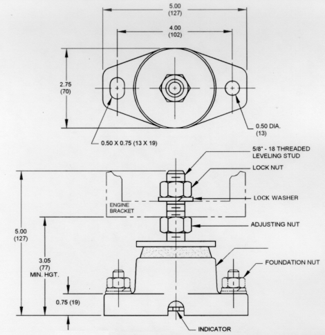
Installation
Procedures |
|
1. |
Temporarily remove the lock nut from the leveling stud. Set the adjusting nut
on each isolator to obtain the same free height. |
|
2. |
Locate the isolators under engine or equipment brackets. Align leveling stud
vertically with mounting hole in engine or equipment. Isolators must have full
load bearing surface under entire length. |
|
3. |
Use deflection indicator as guide, adjust the adjusting nut on each isolator
to obtain even loading and proper alignment. Tighten the lock nut and foundation
nuts securely. The minimum clearance between the indicator and the foundation is
1/8". |
|
4. |
Isolator are now properly adjusted and ready for the equipment to be
operated. |
|